As a member of a six-engineer team, I designed a machine to automatically fret guitar necks. I helped in the system-level design process with the entire team, as well as completing detailed design on some of the most challenging parts of the machine with one of my teammates. This page will guide you through some of the problems that needed to be overcome, as well as the design solutions that were used. In the images below, I have tried to give the best views of the components, which necessitated hiding others.
Problem
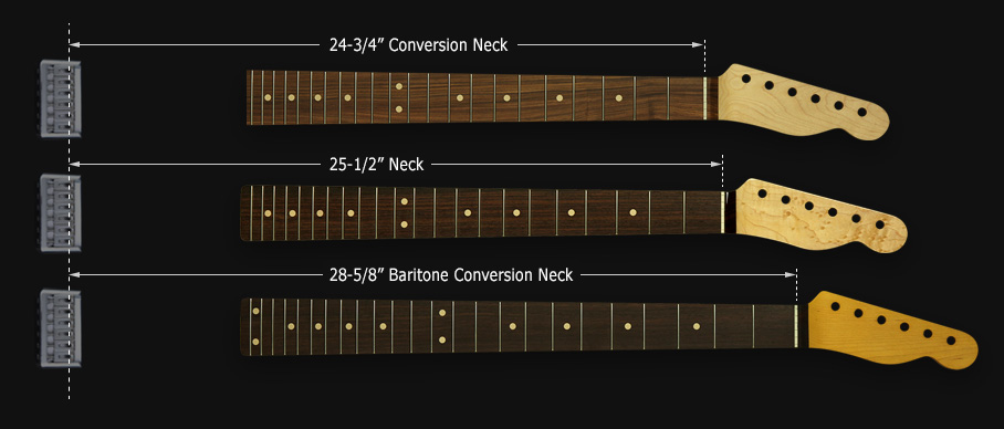
Guitars have metal frets along the neck that act to shorten the string at the correct lengths for each note. The distances between frets are variable and are determined by the overall length of the string, which is the distance from the bridge to the nut, and follows a geometric pattern. Frets must be placed accurately to less than about .03 inches to achieve good intonation. Most guitars are fretted completely manually, and even mass-produced guitars are only partially automated. Our team was tasked with creating a conceptual design for a machine to fret raw guitar necks without human intervention.
The machine was required to complete the following tasks:
1. Cut slots for frets
2. Cut frets from spool of fret wire
3. Place frets in slots
4. Press frets into slots for compression fit
5. Sand edges of frets smooth for safety and playability
6. Move necks from input rack to output rack
Additionally, the machine was required to handle guitars of varying scale lengths and numbers of frets, necessitating a flexible design.


The Design
To achieve the necessary precision and flexibility, our team chose a linear drive to move a single neck down a line of tools. This design affords variation of fret positions for any scale length. The rolling racks on the left and right sides of the machine allow a set of ten guitar necks to be fretted and then rolled directly into the next stage of production. To save space, we chose to place the slotting and fretting tools close together and allow both processes to occur alternately rather than completing slotting before beginning fretting.
Component Design
I worked on the detail design of the fretting tools. The challenge of the fretting tools is that the position of the fret wire is not easily controlled. All other processes in this machine involve linear drives or belts in which the position of the neck is known within one hundredth of an inch. The fret wire, however, is flexible, and must be fed out over the neck to a very small tolerance in order to properly press it into the pre-cut slot without damaging the neck. The task required four separate moving tools to accomplish this.
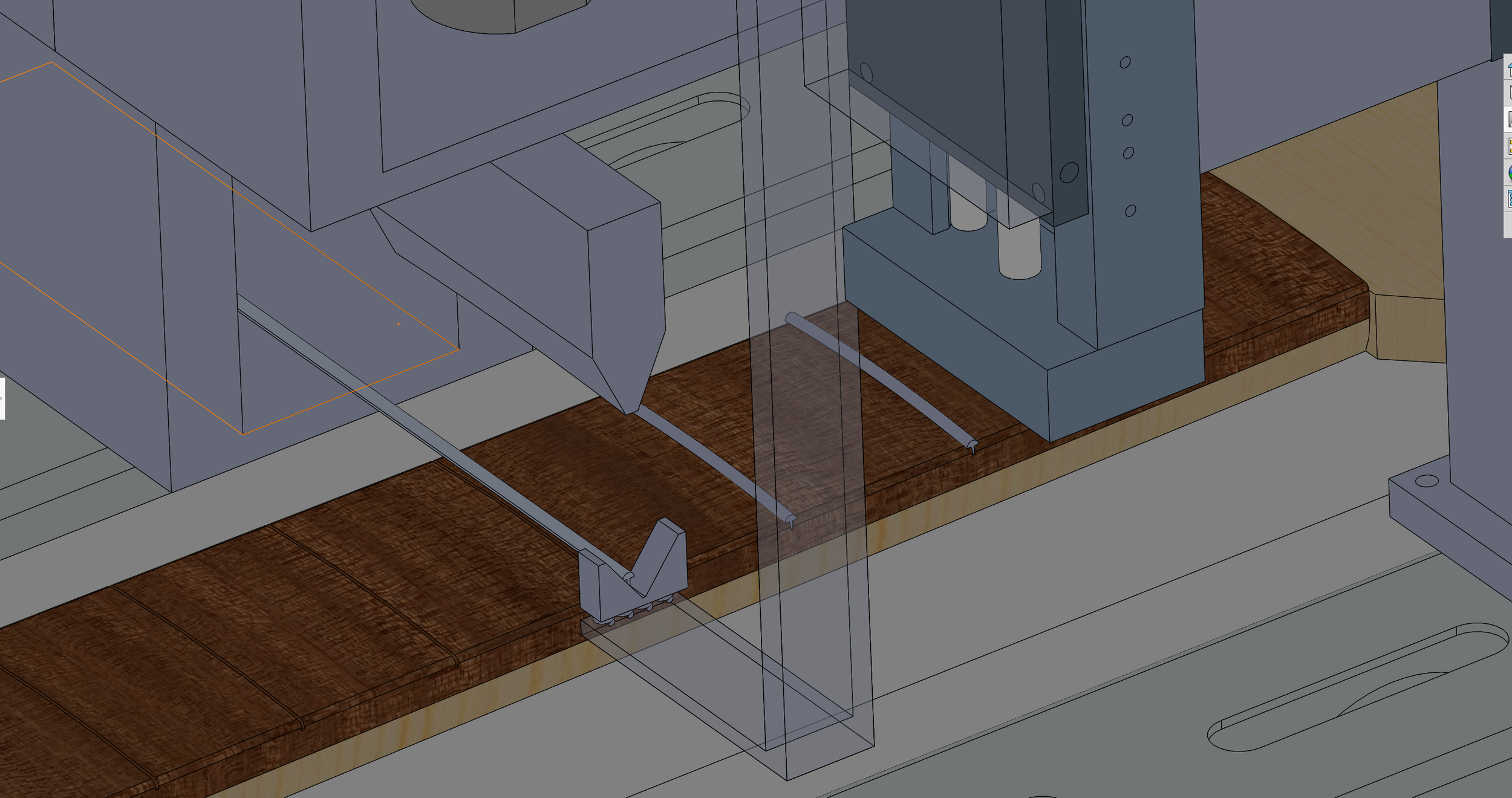
First the fret wire is fed over the neck by a friction drive with grooved wheels that keep the wire straight as it is drawn from the spool. It is shown here with housing in various states of visibility.
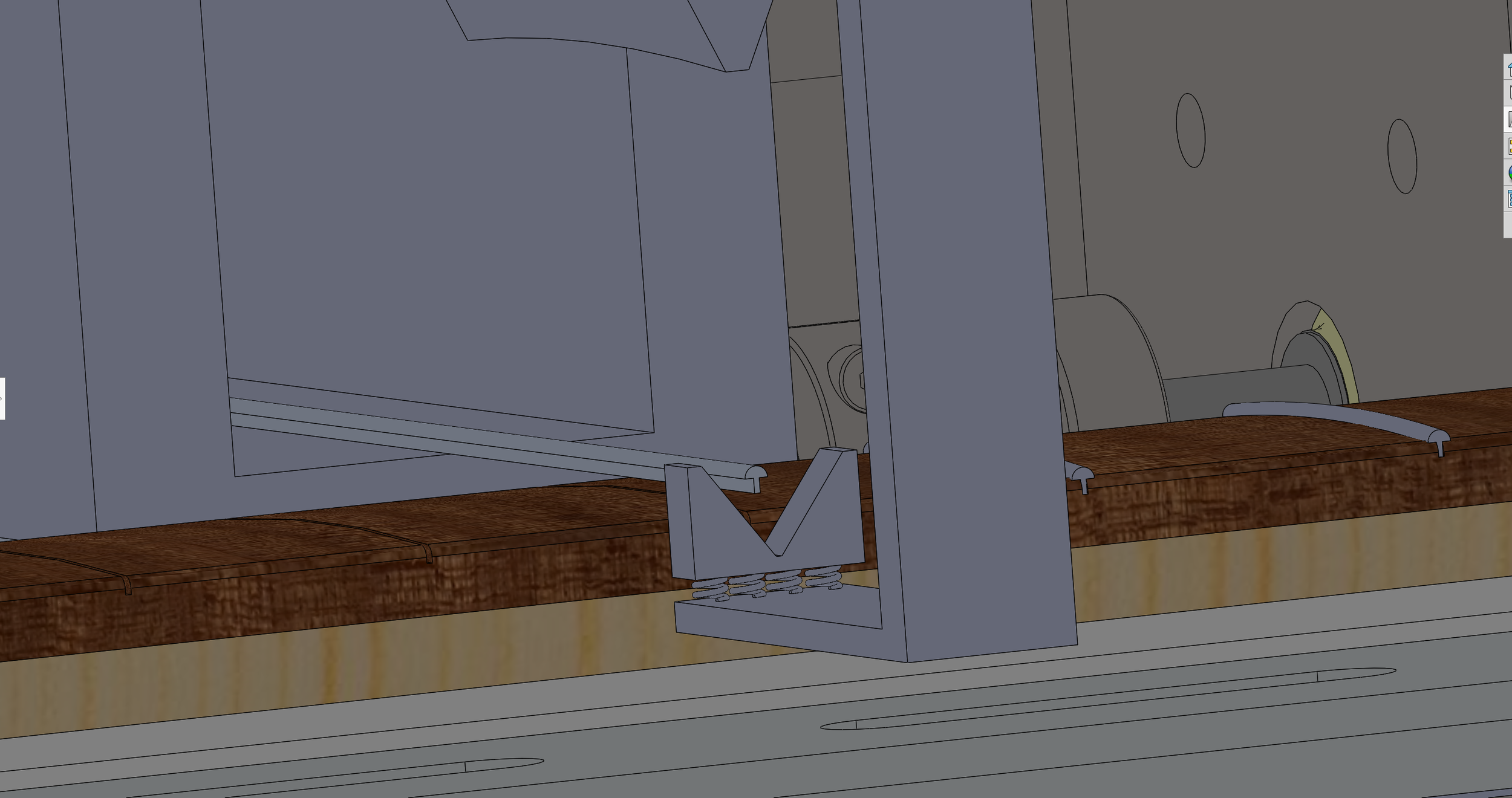
The fret wire is fed out until it reaches the far side of the neck, where it is supported and centered by an angled guide.
Because the amount of wire hanging over the side of the neck must be minimized, the guide must be capable of not only moving vertically to support the wire, but move horizontally toward and away from the neck as the neck profile changes. The angled support piece is also spring loaded to allow it to keep the wire centered over the slot while the wire is pressed into it.
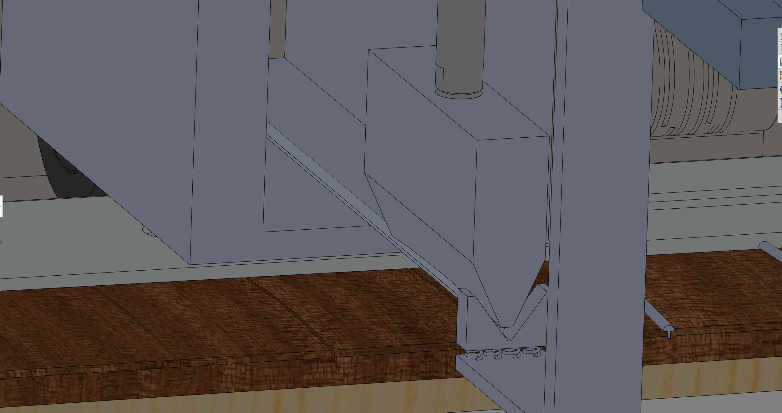
Once the fret wire is positioned over the fret and being held in place by the guide, a rubber press on a pneumatic actuator applies firm pressure from above to fit the wire into the slot.
As the press is raised off of the newly fretted slot, the press is moved aside for the fret wire cutter to approach the neck. The cutter, which is driven by an electrical screw actuator, and the plate beneath the wire, shear the wire very closely to the neck to minimize the amount that must be sanded off later.
This completes the fretting process. After cutting the fret wire, the neck may advance to the next position. The entire fretting tool group may be seen below.


